The Planning/Researching Stage: October 14, 2016 - Now
After much revising and help from our advisors, we feel we have come up with a solid idea. To begin carrying out our idea, we are currently researching viable hardware components for our project, and then choosing and making a list of the final components that will be used. Soon, we will be testing our wireless communication protocol known as ZigBee (using Xbee) to find the range of transmission.
Test 1: Xbee Range Test 1 - October 24, 2016
To begin our testing stage, we first tested the range of Xbee Series 1 at 2.5 Ghz. We found that we were able to transmit a message from about 80 feet (25 meters) away. We tested inside, but made sure the measurement was taken with no walls in between the receiver and the transmitter. From our results, we can conclude that 25 meters will not be far enough to collect data using a drone. Therefore, we will explore other options of Xbees to use in our next tests.
Test 2: Xbee Range Test 2 - November 1, 2016
In this testing state we attempted to retest the maximum range of the Xbee. This time we used a Xbee Series 2 at 2.5 Ghz with larger antennas. We found that we were able to transmit packages from over 120 meters (393 ft) away without errors. That is over 90 feet further than our required 300 ft. We then conclude that we will be using Series 2 Xbees with these antennas, or something similar, in our product.
Test 3: Xbee Transmission Test - November 8, 2016
In this test, wanted to see how long it took for a Xbee to transfer large amounts of data. We found that in API mode it sent max 255 byte packets maximum taking about 2 mins to transfer about 30 kilobytes of data. Which is a rate of 2.09 kbps (kilobits per second). We also tested AT mode where it was able to transfer 15 kilobytes in 18 seconds. Though while much faster, AT mode will not work for our application due to it only being able to work with two specific devices and we plan to use at least 3 different sensor modules.
Future Tests
- Test ability for Xbee to transmit through obstacles (plants, fog, etc.): Our sensor nodes will be placed in the wilderness and thus will have to deal with interference from the environment. We will need to test our nodes in such conditions.
- Test connecting Xbee to microcontroller: We will need to test how an Xbee can be connected to a microcontroller and how well it will work.
- Test power consumption of nodes: The nodes are limited by the range of the drone and the solar power we will be using for the sensor nodes. We will thus need to ensure that the power consumption will be appropriate.
- Test/Calculate packet size: We will need to make sure that the packets are not so big that it will leave the mobile node in one location for too long gathering the data from one sensor node due to the limitations by its battery power.
Test 4: SD Card Test 1 - January 2 - January 16, 2017
The original plan for this portion of the device was going to involve a PIC18F45K22 microcontroller and an external SD mount. Programming the system to save files on an SD card can be challenging and is beyond the scope of our knowledge, so we must use a library that will do all of this for us. First we set up the device with the previously mentioned PIC and tried using a library provided by Microchip, but found that it only officially supported certain controllers. We found a third party library (FatFs by elm-chan) that was universal for any controller, but was unable to get even that to function. We tried again with an external oscillator as the clock (once with a crystal and again with signal generator) thinking that the clock wasn't a nearly perfect square wave which is required for SD cards to function, but was still unable to save anything on the card.
There is obviously a way to make this work, but due to time constraints we had to switch to the WF32 board by Digilent (see appendix). This board has a built on SD card mount and a controller with a bootloader that has a predefined SD card library explicitly made for its controller. We were able to easily get it to function and saved a text file with "hello world" written in it. After that we were able to save a fake data (ie defined in the code, not actually measured) as a csv (comma-separated value) file which can easily be converted into an excel file for the user
There is obviously a way to make this work, but due to time constraints we had to switch to the WF32 board by Digilent (see appendix). This board has a built on SD card mount and a controller with a bootloader that has a predefined SD card library explicitly made for its controller. We were able to easily get it to function and saved a text file with "hello world" written in it. After that we were able to save a fake data (ie defined in the code, not actually measured) as a csv (comma-separated value) file which can easily be converted into an excel file for the user
Test 5: Xbee Range Test 3 - January 26, 2017
We performed a range test while using Xbee Pro S3Bs, which operate within a 900 MHz RF range. We expected the distance before packets were lost to be much farther than with the Xbees we were previously testing, however they had about the same range.
Test 6: SD Card Test 2 - January 29, 2017
Our next step in our project was to test what would happen to the data being stored on the SD card if we had both the mobile node and sensor node continuously running over night. We have had success with both them running for a couple minutes, but have not seen the effects of it running for a long period of time. We had them running over night, while the data was sent every 30 minutes. Unfortunately when we checked the SD card, no data had been saved. There may be a problem in our code with the use of delays.
Test 7: Power Test - February 10, 2017
In these tests we measured the power consumption of both the mobile and sensor node's power consumption so that we could be sure that we could provide enough power for a long enough time for our devices to be effective. The sensor node must be powered indefinitely via a solar charged battery, while the mobile node is powered by the battery of the drone. The sensor node must not drain the battery faster than it can be charged, while the mobile node must not use so much power that it prevents the drone from completing its flight. To measure the current and power of the sensor node device, we connected it to a 3.3 volt power supply. Once the sensor node was powered on and working, we read the current of the device from the power supply unit for when the device was transmitting and when it was not. We found the current when the sensor node is transmitting to be 0.04 Amps. When it is not transmitting, that is, idle, it produces a current of 0.03 Amps. Using the power equation, P=VI, the power of the device while transmitting is 0.1328 Watts and 0.0996 Watts while not transmitting.
Test 8: Xbee General Test - February 12, 2017
Our devices (the mobile and sensor nodes) will be communicating via the ZigBee protocol via a transmitter called an Xbee. This test simply tested range and transmission rate. We need to be able to send actual data via the circuitry we will be using for the actual devices and not with the testing boards and laptops we were using for these early tests. We set up preliminary circuits to allow us to do these tests and coded the controllers on them to use the Xbees to transmit a packet of fake data from one sensor node to the mobile node. In the test, we simply had the sensor node broadcast the packet continuously every 2 seconds and had the mobile node receive the packet and save it to the SD card continuously. We were able to successfully do this test repeatedly.
Test 9: Mobile Node Dimensional Measurements - February 15, 2017
The Mobile Node will be placed on a drone to be carried to each Sensor Node due to them being placed far out in the wilderness. Drone can be very sensitive about the dimensions and weight of their payloads and thus we must ensure that the mobile node isn't too big or too heavy to be carried by a drone. The mobile node device has a length of 8.9 cm, a width of 5.3 cm, a height of 2.9 cm, and a weight of 90.17 grams.
Test 10: Solar Charge Test - February 5 - February 26, 2017
To power our sensor nodes at each station, we will use a solar panel and lithium ion batteries. For our initial tests, we used a 2.5W 5V/500mAh solar panel and two 3.7/1200mAH lithium ion cell batteries in parallel. In between the solar panel and batteries is a 5V charger board, used to charge the batteries from the solar panel. From the charger board, we connect it to a 3.3V step-down converter, which powers the sensor node.
When the solar panel is in direct sunlight it produces over 6V. In our first test we got 6.08V. It also has a current of 0.430 Amps in sunlight. Knowing the voltage and the power, we find that the solar panel produces a little over 2.5 Watts, exactly what we should expect. Having our power circuit connected correctly, we were able to power the sensor node device with no issues while having the batteries charging at the same time. This test indicates that as long as there is sunlight, the sensor node will always receive enough power to transmit and remain on.
To make sure the sensor node can be powered all through the night when there is no sun, we had to check the batteries to make sure they would last at least 12 hours with no power coming from the solar panel. The first batteries we tested were two 3.7V UltraFire lithium ion cell batteries in parallel rated at 1200mAH each. Howerver, after leaving the device running for 10 hours starting at full charge (3.8V), the batteries had depleted to 2.7V, which is not enough voltage to power the sensor node. Next, we tested a lithium ion polymer battery also rated 1200mAH. This time, the battery lasted nearly 24 hours while still providing 3.3V to the sensor node. Therefore, we will be using the lithium ion polymer battery instead of the other two in parallel.
After finding the correct battery to use, we tested both how long it takes the battery to charge and discharge. In full sunlight, we found that the battery became fully charged (voltage of 3.7V or higher) within ten minutes starting from a voltage of 3.2V. This showed that both the solar panel and battery will be be able to provide ample power while in sunlight and charge the battery enough to last overnight.
Test 11: GPS Test - January 5, 2016 - March 2, 2017
The GPS module we chose for our project is the GP-20U7. The first test we conducted with the GPS module was to test if we could get NMEA data from it and display it on a serial monitor. We found that while we were inside, the NMEA data would be incomplete as it could not acquire the satellites. However, when we took it outside, we were able to see the full NMEA data we were expecting. Using several GPS libraries in our code, we were able to get latitude and longitude coordinates.
For the second test, we needed to be able to ensure that the GPS coordinates were accurate. We tested this by comparing the value read from the module with the coordinates from a hand held GPS device. (results here)
For the third test, we needed to measure out the radius required for the mobile node to be within with sensor node for transmission. From previous tests (see test 7), we know that the Xbees can transmit out to over 1000ft, thus we have a lot of room to work with when it comes to the radius around the sensor node we need to make with the GPS. We wanted to test out a 300ft radius, but found it difficult to find a large enough open space for this test. So instead we did a 50ft radius and scaled the measurements to 300ft.
For the final test, we used a preliminary 50ft radius and tested the mobile node's ability to determine its location. When the mobile node entered into the 50ft radius around the sensor node, it began transmitting the flag to tell the sensor node to begin transmitting its data.
Test 12: Long-Term Test - February 20, 2017
It is important to know how long our system can run before receiving errors or missing data. In our preliminary long term test we left our sensor and mobile nodes on all night by plugging them in the computers in the design lab. Our sensor node was transmitting whatever was in its serial port every half hour. We started the test around 7:30 pm on Tuesday February 7. The next day we checked our data around 10:00 am Wednesday February 8 and were pleased that no data was missing or corrupted. Below is a screen shot of the data from the SD card. This preliminary test lasted for about 15 hours. In our next long term test we will run in our test for at least 24 hours while being powered by our solar powered charging system.
Test 13: UAV Test - March 15, 2017
One of the main goals of our project is to have a mobile node attached to a UAV fly over the sensor nodes and collect data wirelessly from the air. Thus, we had to test to make sure this was possible. For this test, we attached our mobile node to an Aerotestra UAV. Once the sensor node was placed on the ground, the UAV was programmed to fly over the sensor node, hover there, and come back. We did this test three times, with each time checking the SD card for the data. The first time we did it, we had the UAV hover over the sensor node for five minutes. The second time, we had it hover for three minutes and the last one, one minute. We found that the mobile device was able to collect all the data within a minute. We were able to collect all the data, but still had a few data corruptions at several time stamps.
Test 14: Moving Mobile Node Test - April 15, 2017
For this test, we simulated what our project is hoping to accomplish. We set up three sensor nodes around Sonoma State University, each with a specified GPS location. The mobile node was moved around by car, and was driven by each of the nodes on the ground. When the mobile node was done collecting the data, a LED would light up to let the driver know to move on to the next sensor node and see how long it takes to collect data. The test was successful, with the environmental data being collected as soon as the mobile node got in range. However, one of the sensor node's battery was not charged fully and thus did not transmit any data. After powering the device to a computer, we got the data. This test showed that our project is fully working.
In this test we used a 50 ft. radius around the sensor nodes, so they would transmit as soon as the mobile node got close enough. We also calculated what a 200 ft. radius would look like, which is closer to what we will be using in the final product.
In this test we used a 50 ft. radius around the sensor nodes, so they would transmit as soon as the mobile node got close enough. We also calculated what a 200 ft. radius would look like, which is closer to what we will be using in the final product.
Test 15: Final Test - April 21, 2017
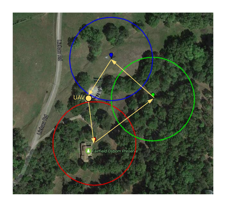
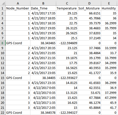
In our final test, we mounted the mobile node to a UAV and set it to autonomously fly to the three nodes. We set the mobile node to begin transmission at 200 ft. Each sensor node was placed at various locations at the Fairfield Osborn Preserve in Rohnert Park, Ca.
The UAV was able to successfully fly to each, it hovered for 10 seconds at each node to ensure a complete transmission. We ran into few problems involving power to the third sensor node and receiving power from the UAV to the mobile node. After a few hours of troubling shooting the problems, we were able to do a successful test, gathering real sensor data from each node. The figure below shows the flight path of the UAV along with the 200 ft GPS radius that the mobile node did the transmission in along with the data from the test after being processed by our Matlab program.
The UAV was able to successfully fly to each, it hovered for 10 seconds at each node to ensure a complete transmission. We ran into few problems involving power to the third sensor node and receiving power from the UAV to the mobile node. After a few hours of troubling shooting the problems, we were able to do a successful test, gathering real sensor data from each node. The figure below shows the flight path of the UAV along with the 200 ft GPS radius that the mobile node did the transmission in along with the data from the test after being processed by our Matlab program.